Wiring
Power, CAN FD, and USB-C on the motor. No on-motor terminator. 40 A breaker. 7–20 V.
Land power, CAN, and USB-C before the first enable. Swapped CAN H/L or a missing terminator fails on the field, not in CAD.
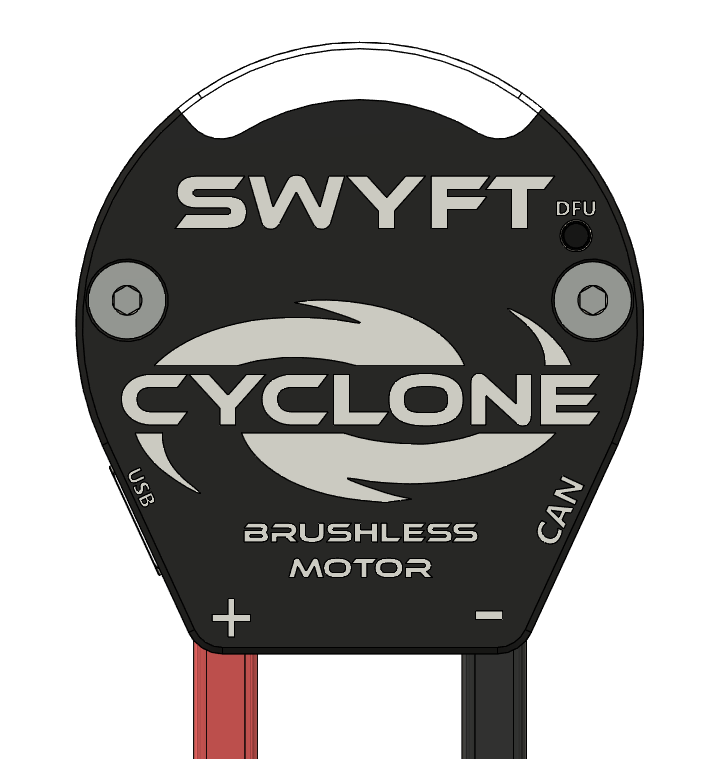
Rear cover
Every marking on the cover is a real port or a real lead. The two silver hex heads are case screws, not mounts — Mounting.
| Marking | What it is |
|---|---|
| + (red lead) | Battery / PDH positive. Flying lead out the bottom of the cover. |
| − (black lead) | Battery / PDH negative. Flying lead out the bottom of the cover. |
| CAN | Side pocket on the right. CAN H and CAN L. No terminator in this port. |
| USB | Side pocket on the left. USB-C. Configuration, firmware, and output. |
| DFU | Pinhole next to a small red power LED. Recovery only. DFU |
| LED window | Seven lights under the white arc. Two ends are controller status. Status lights |
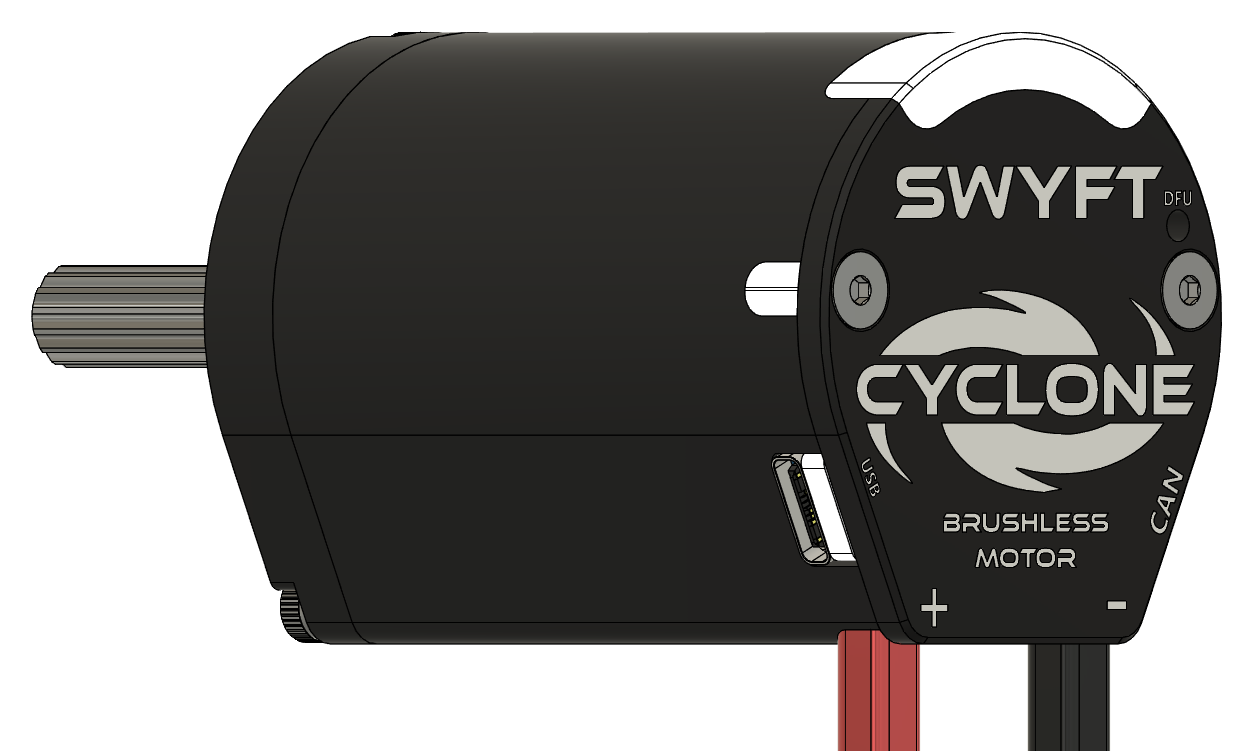
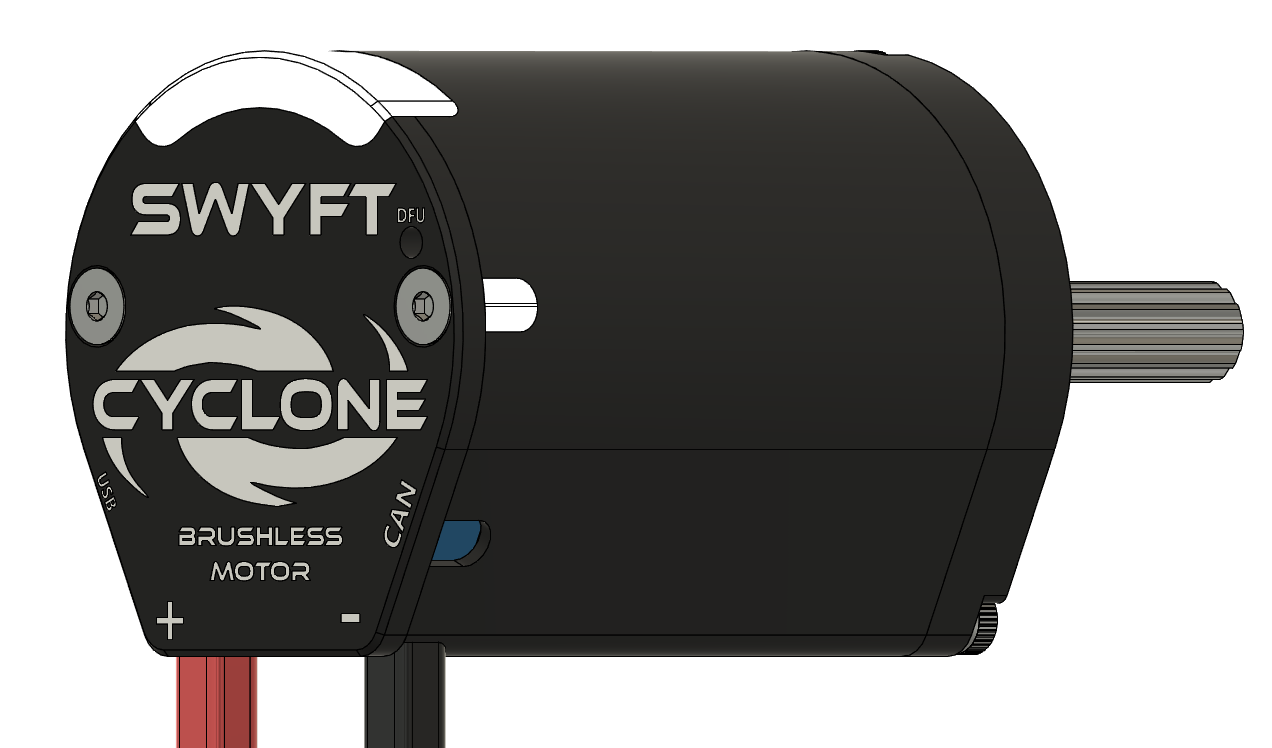
Keep USB-C, the CAN port, the DFU hole, and the LED window reachable after the motor is in a tube. Do not plate over the rear cover with no airflow.
Power
Red is positive. Black is negative. Operate on the FRC 12 V bus, 7–20 V. Outside 7–20 V is out of spec.
One 40 A breaker per motor on the PDH. Supply 40–60 A continuous, 70–80 A peak. Stall is 253 A. The breaker protects the PDH channel. Stator and supply limits protect the motor. They do not replace the breaker. Current limits
On a 40 A run, 10 AWG is recommended. 12 AWG is the minimum on a short run. Keep power leads short. Dress them away from CAN. Crimp a connector that matches the PDH harness. Do not leave tinned flying leads in a match.
The small red LED next to the DFU hole is on when bus power is present. That LED is power, not a status code. LED off and both end lights off: no power. Check breaker, PDH channel, and red-to-+ / black-to-− before you debug CAN or code.
Cyclone is reverse-polarity protected. A reversed pack can still destroy other devices on the same run. Verify red to + and black to − before the first enable.
CAN FD
The CAN port is the side pocket marked CAN. Two conductors: CAN H and CAN L. Crimp them to the same H and L as the rest of the robot. FIRST’s usual convention is yellow = CANH, green = CANL — match the harness you actually built. Swapped H and L: no communication.
No terminator on the motor. Put 120 Ω at both ends of the trunk, not on every device. A star with no end terminators looks like a dead motor.
Assign a CAN ID from 1–62 in SWYFT Link. Every Cyclone on that bus must have a different ID. Duplicate IDs will not run — the end lights go blue together. Status lights
SWYFT Link on SystemCore lists Cyclones that are on the CAN hub. Config, control, and firmware also run over CAN FD. SWYFT Link and DFU
USB-C
USB-C is the pocket marked USB. Full control path: configuration, firmware, and output. Open SWYFT Link in a browser and connect this port.
The motor runs only when the power leads are at 7–20 V (FRC 12 V nominal). USB-C does not power the windings. Confirm the red LED next to DFU is on before you enable.
Do not command this motor from USB-C and from robot code at the same time.
DFU is USB-C only. Disconnect the battery and every other supply on the power leads. No PDH. No bench supply. Procedure: DFU.
Before you enable
- Motor clamped or mounted, shaft free. Mounting
- Red to +, black to −. 40 A breaker in this channel. Red DFU-adjacent LED on.
- If the motor is on CAN: H and L match the bus, 120 Ω at both ends of the trunk, unique ID 1–62.
- Stator and supply limits set for this mechanism — not 160 A stator. Current limits
- Then go to First power-up for the first enable.
NEXT First power-up