Specifications
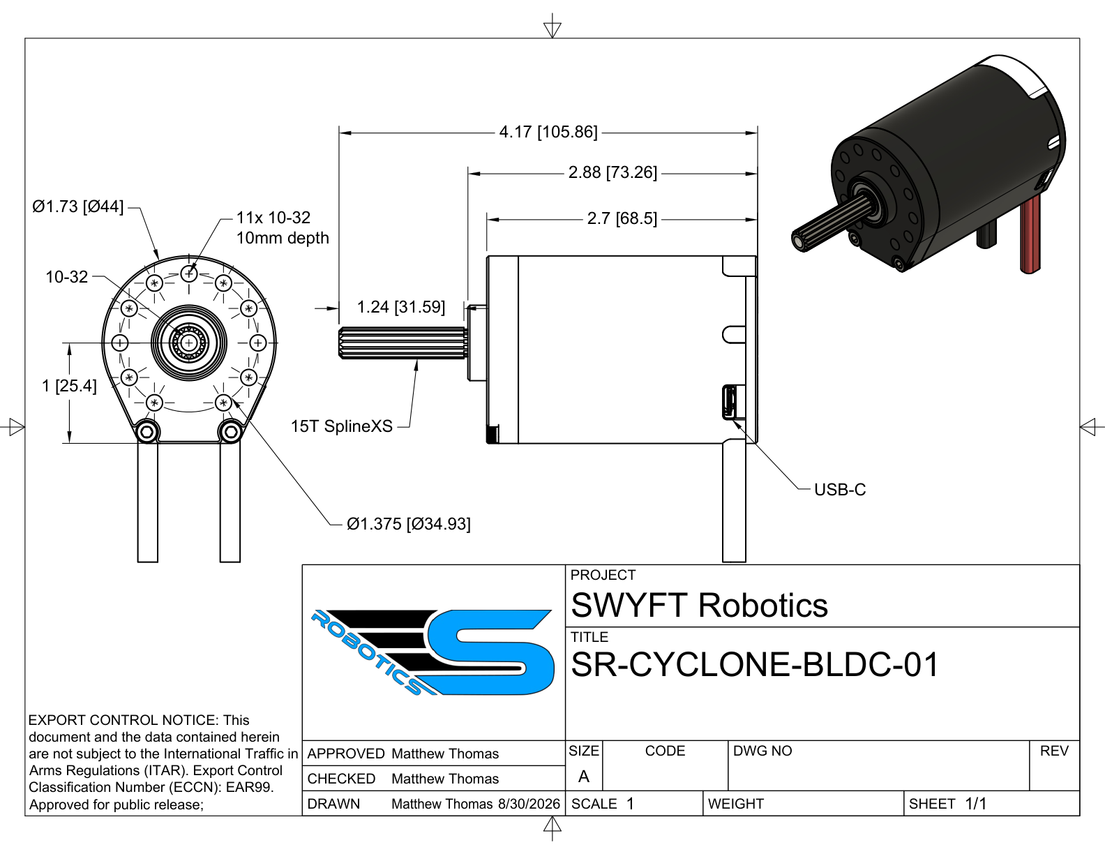
Mechanical
Physical envelope, output shaft, and mounting pattern.
| Parameter | Value |
|---|---|
| Body diameter | 1.73 in (44 mm) |
| Body length | 2.7 in (68.5 mm) |
| Overall length, with shaft | 4.17 in (105.86 mm) |
| Shaft stickout | 1.24 in (31.59 mm) |
| Mounting face to USB-C | 2.88 in (73.26 mm) |
| Output shaft | 15T SplineXS |
| Mounting holes | Eleven 10-32, 10 mm deep, on a Ø1.375 in (34.93 mm) bolt circle |
Electrical
Bus voltage and the currents the motor draws and limits.
| Parameter | Value |
|---|---|
| Nominal bus | 12 V (FRC) |
| Power-input protection | Reverse-polarity protection. Connect red to positive (+) and black to negative (−). |
| Stator current limit | Configurable, 0.001–50 A; verify the live setting |
| Supply current limit | Configurable, 0.001–35 A; verify the live setting |
The Cyclone limits two distinct currents. Stator current flows in the windings and sets torque; supply current is what the battery delivers. Duty cycle links them: supply current is approximately stator × duty, so a large winding current draws only a small battery current at low duty. Near stall at about 10 % duty, roughly 70 A in the windings corresponds to about 7 A from the pack. Set the stator limit to protect the motor and the supply limit to protect the battery and breaker.
Mechanism performance
Choose gearing and current limits for the load and measure the result on your robot. A software current-limit ceiling is not a continuous-current or stall-performance rating. This reference does not provide a verified torque-speed curve.
Control and sensing
The control modes, and the encoder behind them.
| Parameter | Value |
|---|---|
| Control modes | Duty, velocity, position (public Java API) |
| Encoder | 14-bit absolute magnetic, 16,384 counts per turn |
| Commutation | Trapezoidal: the controller switches the motor coils in a repeating sequence using encoder feedback. |
Duty requests a signed output fraction. Velocity uses rotor RPM; position uses rotor radians and requires configured gains and a known mechanism reference. Public Java current control is not supported. See Control requests.
Communication
How the robot reaches the motor and addresses it on the bus.
| Parameter | Value |
|---|---|
| Interfaces | CAN and USB-C |
| Both interfaces | Control, configuration, telemetry, and updates; available operations depend on the release |
| CAN wiring | H (yellow), L (green); two 2-pin Molex connectors, one male and one female |
| Device number (CAN ID) | 1–62 |
| Control system | 2027 SystemCore |
Thermal
How the motor protects itself as it heats up.
| Parameter | Value |
|---|---|
| Over-temperature warning | 65 °C default, configurable 40–80 °C |
| Over-temperature trip | 80 °C. Output is cut. |
| Thermal fold | With thermal fold enabled, the allowed stator current decreases between 70°C and 75°C, reaching 12 A |
Thermal derating means reducing the allowed current as the controller board gets hotter. With default fold settings, the stator ceiling decreases from 70°C to a 12 A floor at 75°C; a lower base is not raised. A separate sustained 80°C condition stops output. See Power & thermal budget.